
- Electrical plan symbols install#
- Electrical plan symbols professional#
- Electrical plan symbols download#
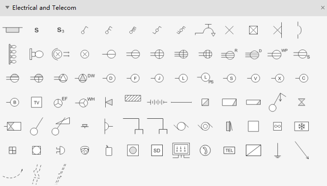
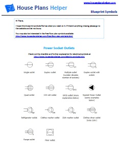
The standard unit is the ampere, symbolized by A. The common symbol for current is the uppercase letter I. The most commonly used electrical blueprint symbols including plug outlets, switches, lights and other special symbols such as door bells and smoke detectors. A plan, drawn to the same scale as the working plan, that shows the position of all electrical apparatus installed underground except signals and telephones. You can depict a complex electrical circuit with the standard and simplified electrical symbols.
Electrical plan symbols professional#
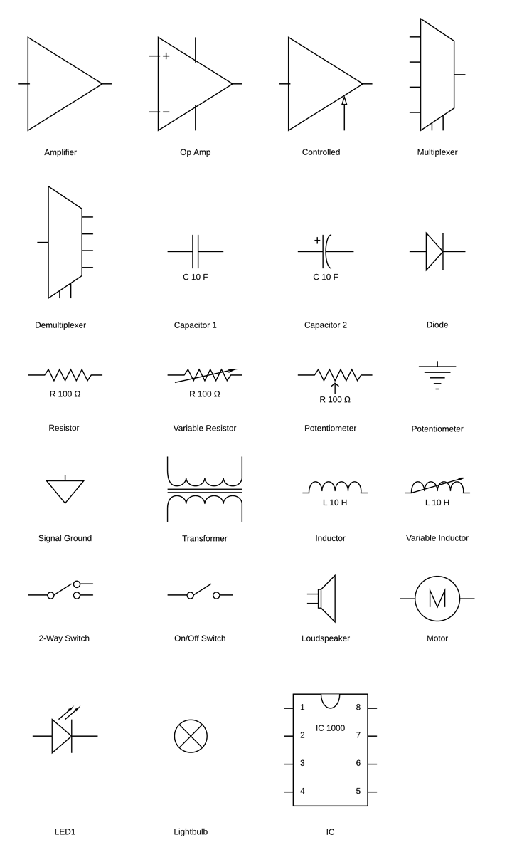
Whether you are a novice or a professional engineer, these basic symbols can help create accurate electrical and circuit diagrams in minutes.

What is an electrical plan?ĭefinition of electrical plan. Basic electrical symbols contain earth electrode, cell, battery, resistor, etc.

Allows current flow in one direction, but also can flow in the reverse direction when above breakdown voltage. The plan is often termed as electrical plan. Diode allows current flow in one direction only - left (anode) to right (cathode).
Electrical plan symbols install#
In general, to install the electrical appliances and machines for any home or industry initially a plan is made by Engineer.
Electrical plan symbols download#
What is an electrical design plan?Įlectrical plan is “a preplan of electrical design on a paper before the physical installation of electrical appliances and machines in real time”. 238133 Best Illustrator electrical plan symbols free vector download for commercial use in ai, eps, cdr, svg vector illustration graphic art design.

For clarity, it is recommended that the electrical symbols be drawn darker than the back-ground drawing showing the building structure and/or other systems. We will begin with adding switches by the front door. The below architectural symbols, are broken down into the following categories: Services symbols Lighting symbols Electrical symbols Plan, elevation and section symbols Service symbols Service symbols represent the mechanics of a building, and help to identify such elements as mechanical ventilation, soil pipes, and incoming power for example. We should remove the dimension, door, and window symbols. In order to obtain a building permit, you will need a set of plans that show your local building department what you are planning to do. We open our Living Room plan that we drew previously and save the drawing as our Electrical Plan. Identify the standards and regulations that guide the electrical design process. If you are planning to build a new home, add an addition or perform a major remodel, you will need to obtain a building permit. Recognize the symbols used in electrical plan design. Refer to the symbol sheet for special symbols used in a particular set. Electrical Symbols For Building Plans For A House - Part 1 Part 2. It might look fairly simple to most, but it actually stands for “three-phase, open delta, grounded at common point”.Ĭan you imagine what an electrical schematic might look like if there were descriptions like this all throughout the diagram? To circumvent this would-be headache, electrical engineers are carefully trained to recognize these symbols, identify their meaning, and understand their relationship to other nearby symbols.Frequently Asked Questions What is the purpose of electrical symbols on plans?Įlectrical symbols are used on home electrical wiring plans in order to show the location, control point(s), and type of electrical devices required at. a) Electrical systems should be shown on plans sepa-rate from the architectural, structural, mechanical, and other systems. Every engineering office uses their own set of symbols however, the symbols below are fairly common across many offices. If it’s just a visual meant to show how the wires and components are laid out and connected, it’s referred to as the latter.Įach symbol in an electrical schematic has its purpose and is used to replace the need for what would otherwise be text-heavy descriptions.Ī good example is the electrical symbol below. The difference between an electrical schematic and a block / layout diagram is that the former shows the actual electrical connections. An electrical schematic diagram might look like a nonsensical drawing to the layman, but to the electrical engineer, it’s a high-level documentation that provides a ton of insight and instruction.


 0 kommentar(er)
